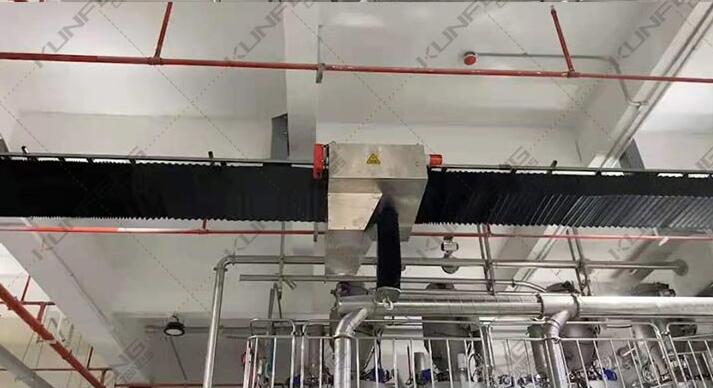
Product Overview of Low Headroom Suspension Cranes
1.1 Main technical conditions
The design and manufacture of the low-headroom single-beam suspension crane follows the JB2603-94 standard of "Electric Single-beam Suspension Crane". Generally, the crane is 0.5~10T, the span is 3~22.5m, and the running speed is 20m/min and 30m/min. If there are special requirements, it can be designed and manufactured separately.
1.2 Scope of use
The working level of the low-headroom suspension crane is A3~A5, the working environment is -25℃~45℃, and the relative humidity is ≤85%. Use with caution when melting metal and drama items! Low headroom electric suspension cranes are widely used in industrial and mining enterprises, warehouses, material yards and other places because of their compact structure, good rigidity, sensitive operation, low noise, no pollution, safety and reliability. The crane working power: AC 380V 50Hz, can also be customized according to customers.
1.3 Basic structure
The low-headroom suspension crane is mainly composed of main beam, end beam, electric trolley, electrical appliances, and hoisting structure. The electric trolley is common to the CD1 trolley, and has good versatility and interchangeability. In general, the span of 0.5t is 3~16m: the span of 1t is less than 12m; the span of 2t is less than or equal to 7.5m. The wheel base of the beam varies with the weight and span of the crane.
Installation and debugging
In order to facilitate transportation, the main beam, end beam, electric hoist, and electric (slave) moving trolley are generally disassembled and packaged when leaving the factory, and are reassembled during on-site installation.
A. Main beam and end beam assembly
There are three shaft holes at both ends and in the middle of the main beam. Insert the connecting plate into the gap in the middle of the main beam. After the hole of the connecting plate is aligned with the same aperture in the middle of the end beam, install the shaft II, and then use the card plate to fix the shaft II. Can.
B. The electric trolley (driven trolley) is connected to the main beam:
The connection between the trolley and the main beam is completed by the triangular balance beam axis I, M30X1.5 bolts, etc. According to the width of the trolley track, use the adjusting pad to adjust the distance between the inner edge of the wheel and ensure that the inner edge of the wheel is 3~5mm away from the track edge.
C. Electrical and electrical installation
After each part is installed, set up electrical appliances and circuits in the correct installation. The metal casing of all electrical equipment on the crane must be effectively grounded, and the crane's track should be permanently used as the ground wire. The total ground resistance shall not be greater than 4Ω.
D. For the installation and debugging of the lifting mechanism, please refer to the relevant electric hoist instructions
E. Crane's requirements for rail installation accuracy
1. Track span deviation ±2mm;
2. Track horizontal inclination ≤ 1/1000;
3. Track joint deviation: 2~3mm;
4. Track bending deviation: ±2mm;
F. Debug
