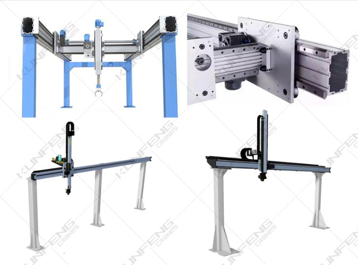
The Gantryrobot consists of a structural frame, X-axis components, Z-axis components, fixtures and control cabinets.
in:
1. The structural frame is mainly composed of structural parts such as uprights. Its function is to lift each axis to the corresponding height, and it is mostly composed of welded parts such as aluminum profiles or square tubes, rectangular tubes, and round tubes;
2. The X-axis component, the Z-axis component, and the two motion components are the core components of the truss manipulator, and their definition rules follow the Cartesian coordinate system.
Each shaft assembly usually consists of five parts: structural parts, guide parts, transmission parts, sensor detection components and mechanical limit components.
1) Structural parts are usually composed of aluminum profiles or square tubes, rectangular tubes and other structures. Its function is to serve as the mounting base for components such as guide parts and transmission parts, and it is also the main bearer of the load of the Gantryrobot.
2), guides, commonly used linear guides, V-roller guides, U-roller guides, square guides and dovetail grooves and other common guide structures, the specific application of which should be determined according to the actual operating conditions and positioning accuracy.
3) Transmission parts usually have two types: electric and pneumatic. Among them, electric has rack and pinion structure, ball screw structure, synchronous belt drive, traditional chain and wire rope drive.
4) The sensor detection element usually uses U-shaped photoelectric switches at both ends as the electrical limit. When the moving component moves to the U-shaped photoelectric switches at both ends, the system alarms; in addition to the electrical limit, there are also fixed mechanical limits. To prevent electrical limit failure, the mechanism is locked to prevent its overtravel; in addition, there is an origin sensor for origin search.
5), the mechanical limit group, its function is the rigid limit outside the electric limit stroke, commonly known as the dead limit.
3. Tooling fixtures have different forms according to the shape, size, and material of the workpiece, such as: vacuum suction cup suction, chuck clamping, holding and pin-type fixture insertion and other forms.
4. The control cabinet, which is equivalent to the brain function of the truss manipulator, is realized through the special controller of the truss (such as PLC, motion control, etc.), collects the input signals of each sensor or button, and sends instructions to an executive element according to the predetermined action to execute,
Complete the joint movement between the X and Z axes, so as to realize a complete set of fully automatic operation process.